|
|
Post by bigmal on Feb 19, 2006 9:28:14 GMT -5
Thank you for the reply MiNiTiCi, That is what I thought the answer would be, All the very best.
|
|
gator
New Member

Posts: 4
|
Post by gator on Jan 15, 2007 22:10:47 GMT -5
Hi All.
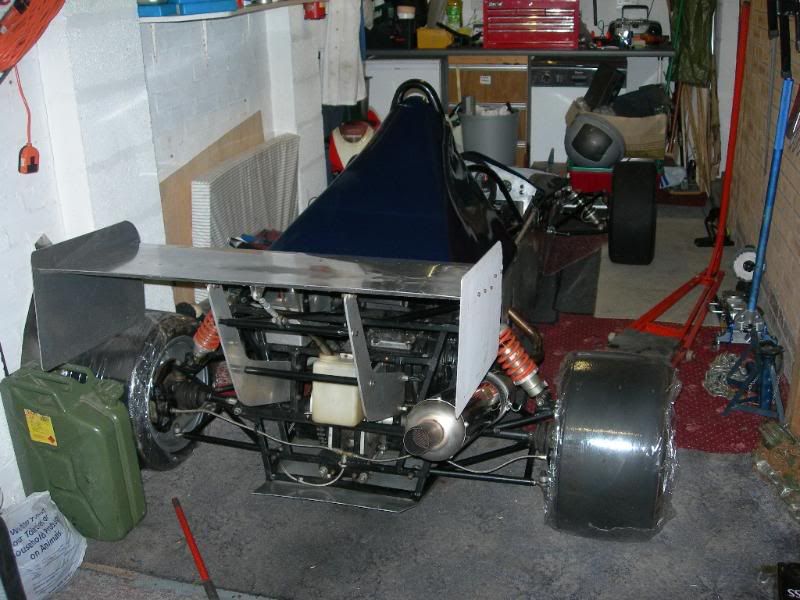
I am finally making a start so excuse the ramblings as I will be taking some liberties, the cockpit is around 900mm wide (2 seats) and the rear section will be a fair bit different to accept a larger engine lump. But it follows the original Terrapin layout wherever possible.
A decision yet to be made on whether to use a rod end (as per picture) on both top and bottom of the upright or top only. Are there any angularity issues generated by using a rod end on the bottom? as the standard ball joint is set at a fair angle.
(For the record I am playing with a drum braked mini upright which I hope will accept an ally bracket to take a Wilwood caliper and disc).
On the subect of pick up points, I will be using 13in wheels (20 in overall with slick tyre)...any thoughts out there on what this does to the "book" location points?
What is the overall height of the 10in original anyway?
Finally, I notice that the reversing of the mini upright for front steer would appear to give the reverse of Ackermann. I was planning to reverse the arms as well so they point outwards, space permitting.Any comments of how this works in reality?
I would appreciate any thoughts.
Regards
Alan
|
|
wig
New Member
Teme valley Terrapin
Posts: 32
|
Post by wig on Jan 17, 2007 2:56:41 GMT -5
Im unsure about your rod-end/ balljoint query as my car runs balljoints top and bottom.
However the ackerman issue i can certainly answer for you. No you simply cannot turn the arms round the opposite way because they wont fit, without hitting the disk.
You can heat them and straighten them out, as long as you allow them to cool as slowly as possible ie. in the oven or submerged in a bucket of sand, to ensure you dont harden the material off too much!!
This will get u most of the way there, if however you feel uncomfortable about this, as i did, you can fabricate some from 3/4"+ H30 grade aluminium bar, just appropriatley drilled for the relevent mounting bolts, and cut to a similar length as the original arms.
With all of this bear in mind that this only works to its fullest efficiency when the rack arms are running parallel to the front axleline when viewed from the aerial position!
To get an idea of where the optimum steering arm pick-up position is, draw imaginary lines from the centre of the rear axleline through the top balljoint centre, the rack arms should pick up where these lines disect the steering arms.
Hope this helps.
Also I can supply some arms the same as mine to you for a sensible cost + carriage if you at all interested.
|
|
Ian
New Member
Posts: 14
|
Post by Ian on Jan 19, 2007 14:08:55 GMT -5
Modern thinking has moved the itersection point forward of the rear axle by as much as 50%. this is because the George Lankensperger/Rudolph Ackermann classic formula did not take into account the introduction of pneumatic tyres. Calculated Ackermann does not take into account the fore and aft movement of the tyres when they are steered. The formula can also be improved by considering the effect of scrub radius. Racing tyres operate at significant slip angles, the original formula ignores this. Several of these significant developments were made while preparing the SAE technical paper 2006-01-3638 entitled Analysis of Ackermann prepared by Allan and myself. An enhanced Jeantaud diagram was developed after the initial draft and the mathematical relationship verified by William C Mitchell. Hope it hasn't caused confusion but it is developing topic for discussion. Ian Scott
|
|
|
|
Post by razzaq on Apr 7, 2008 0:40:34 GMT -5
Hi, This post of yours is very beneficial and informative, however there are some specific information that I require. If anyone can help me in this matter then please send me a private message.
Best Regards,
|
|